Light Controller Example
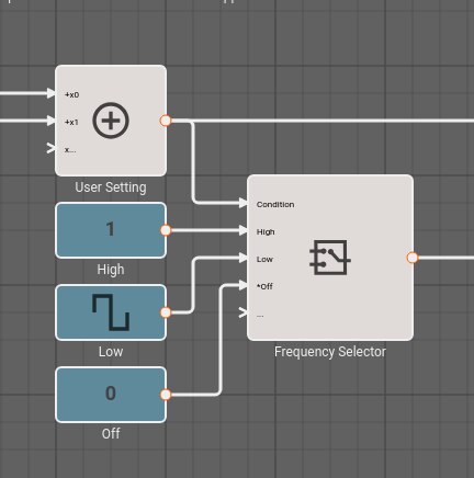
Here is a simple application to control a light. The light is controlled by a switch and it can be bright, dim, or off. Diming is accomplished by rapidly turning the light on and off.
The switch output is represented by inputs x0 and x1 entering from the left. The User Setting (Sum) block combines them to produce a value of two, one, or zero. A signal determining whether the light is on or off exits on the lower left. The signal on the upper left is for inspecting the input and can be ignored.

The User Setting is encoded thus,
| Setting | Value |
|---|---|
| Bright | 2 |
| Dim | 1 |
| Off | 0 |
The User Setting block supplies the Condition input to the Frequency Selector (Switch) block, which selects one of its other inputs to pass to its output.
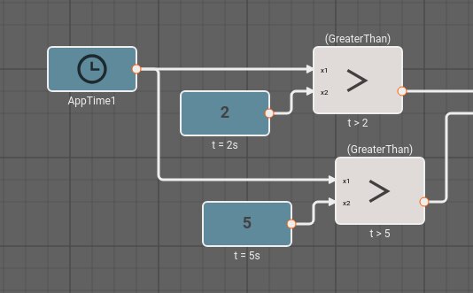
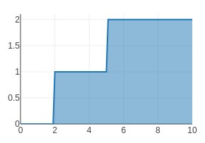
The input to the application is simulated for ten seconds. The light is initially off, after two seconds, it is dim, and after five seconds, it is bright. The simulated input can be derived from the application time.

The idea is that the switch is wired so that when the dim setting is selected, the switch has one output high, and the bright setting has outputs both high. The sum of the user input over time is shown in the plot below.

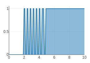
To control the brightness the application selects one of three signals values. The bright signal is always on, the dim signal is on half the time, and the off signal is, well, always off. For illustration, the dimming frequency is low, so there is no need to zoom in on the signal to see it pulse on and off.

Notice how the output is initially off, from two seconds to five seconds it pulses on and off, and after five seconds, it is solidly on.

In a real application, the inputs would come from GPIO Input blocks, and the output would go to a GPIO Output block. The output would control a solid-state relay to control the lamp. The square wave would have a frequency high enough that the flickering was imperceptable. Alternatively, the inputs could come from bus protocol block such as I2C Input or CAN Receive; and a PWM could be used instead of the square wave.